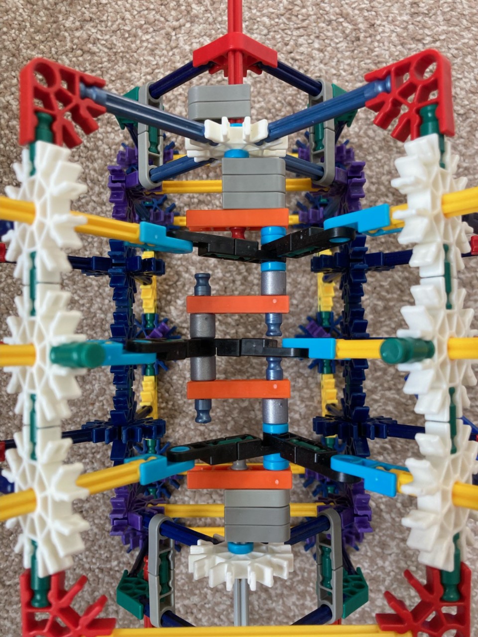
I made this Knex V6 engine
Monkey boy is old enough to sit and play constructively for a while, which means I can build fun things next to him.
I wanted to make something that turns circular motion into reciprocating (linear) motion - like a piston - because I’ve never done that before, and I don’t know how they work (but I thought I could guess).
My goal was to build a multi-piston engine without looking at any drawings or examples.
Well, it’s not really an engine. There’s no combustion. And rather than the piston movement driving an axle, the axle drives the piston motion. “It’s a puppet!!”
While writing this post, I’ve looked up a few things to find some better words for the parts of the finished machine.
Touch/hover the image to play a looping video (or view knex-engine on Glitch):

Design Challenges
I went through several prototypes, from a simple two-piston design to the final product.
Where to start
First, I worked out how a piston goes in and out from a rotating bar:
- Add an offset to the rotating bar (a crank)
- Connect the piston to that via something that can hinge
Crank
In my first versions, there was a single offset crank, and every piston connected to it with a simple grey end clip. Two grey clips each occupy one “unit” of space on the crank, but the piston exits are symmetrical, so the bars going each way were slightly twisted.
I figured out I could use a Knex hinge half, so that two rods could share the same space on the crank.
At this point I scaled up to six pistons, but the crank was “heavy” at the low point, because the load wasn’t even at each part of the cycle. Also, all the pistons on one side fired at the same time. You can click that link for a video of the sad crank in version 2 of the V6.
I figured out I needed opposite offsets to the cranks:

As you can see, space is limited. There isn’t the room to connect things in the way you might ordinarily do with Knex, so I arranged spacers to push all the parts together and into the right gaps; the two middle pistons have exactly enough room to pass between the neighbouring blue rods, and no more!
That arrangement is the part I’m most proud of.
Valves rotating
I’m going to call the white snowflakes on the top “valves”. The pressure of the pistons moving through these made them want to rotate. If they do rotate out of place, the whole thing stops. I had to find a way to hold them in place that was strong, but also let you see some of the internals. In this final design, I support them with rods from above and below in a strong triangle, and connect those braces together laterally so there’s no wiggle.
I also chose to clean the white valve pieces and the yellow rods with soap and water to reduce friction; most of my Knex collection has been heavily played for 20 years. I considered WD45 but that seemed a little over the top 🙂🙂🙂
Wobbling axle
Last and simplest, the axle wobbled at each end if it only passed through one connector hole. So, I spaced out two connectors to hold it steady, which you can see at the top and bottom of the pic above. This bit could probably be miniaturised a little more.
Conclusion
This was a fun engineering challenge and I enjoyed what I learned. That’s it. Thanks for reading my nerd blog! ⚙🗜🔥😎